back to Page One
to Page 2 Initial Testing
to Page 4 Final Design
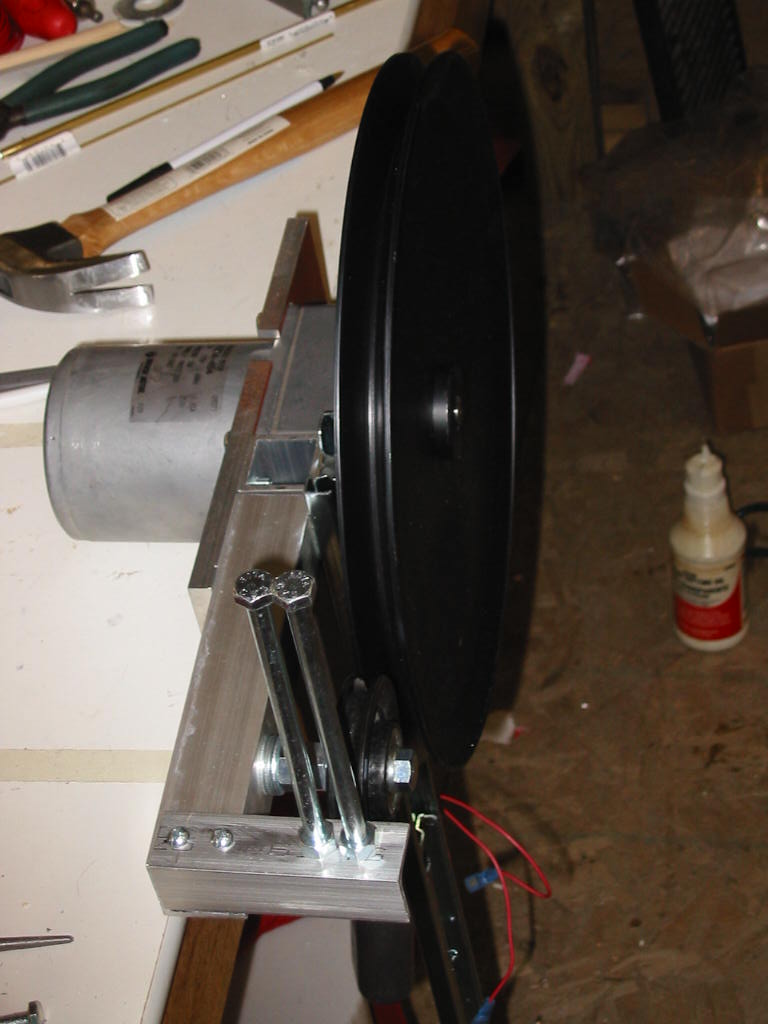
slow down the ghost to make it easier to control.
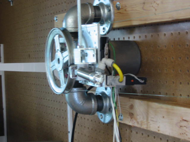
limit switch will stop the motor in that direction and activate the air
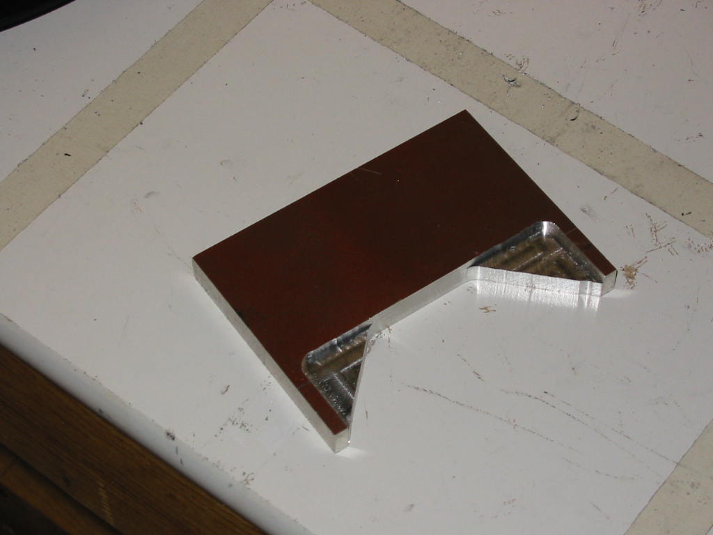
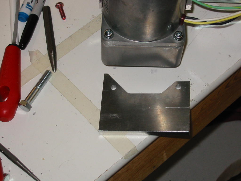
cylinder to stop the line more quickly. The bolts act as a line
guide for the 50 lb fishing line, otherwise the fishing line would be
pulled over too much and jump off the pulleys.
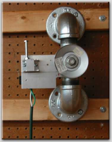
Maybe by adding some end cushions for the line tightener/pulley
mechanism, the pulley brake may not be needed.
line. A little crude, but it gets the job done.
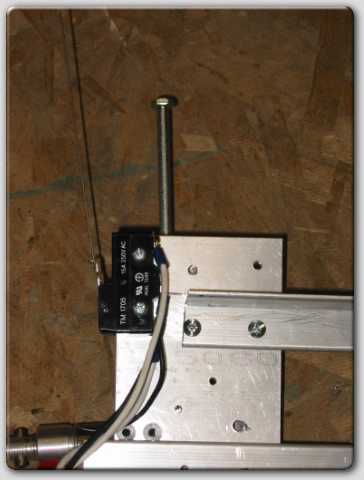
showing the limit switches for the
end of run stopping.
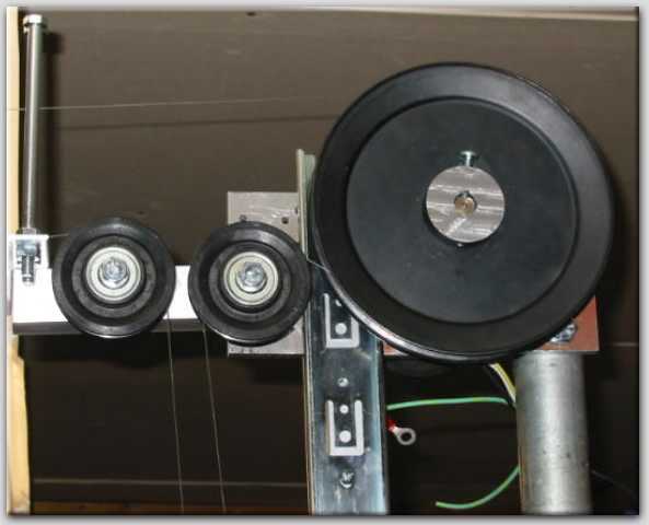
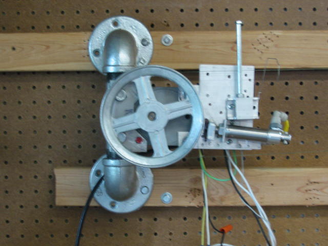
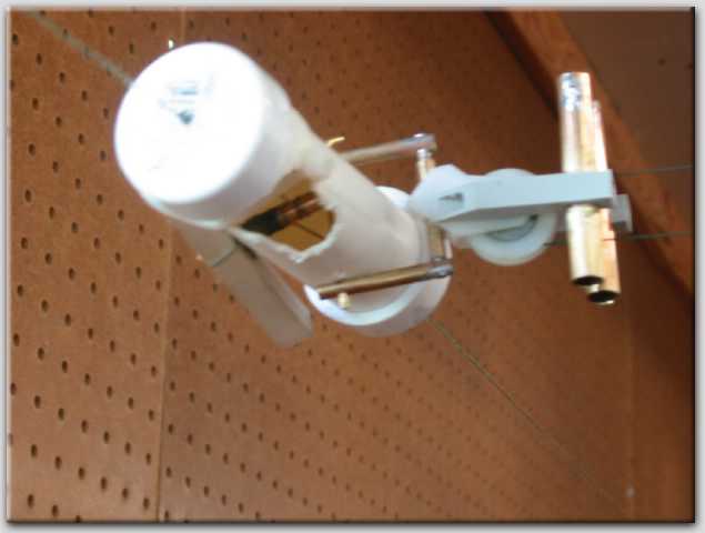
in and out. Here too, I went to a smaller pulley for less speed.
The small middle pulley was needed to wrap the line around the bigger
pulley for better traction. Not shown, I did glue in a leather cord inside
the larger pulley otherwise the line would still slip due this line does not
have that much tension on it.

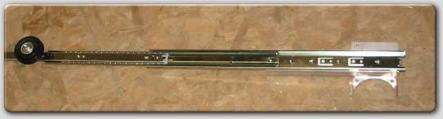
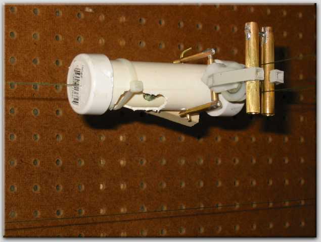
left/right line and needs to lengthen out when it gets to either the far left or right side.
The slack adjuster is made from 2 drawer slides. The photo above is a single slide
and I ended up adding a second slide onto for more travel when/if needed later on.
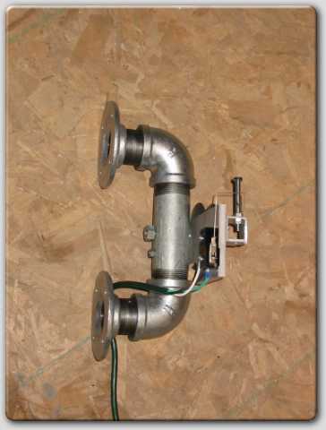
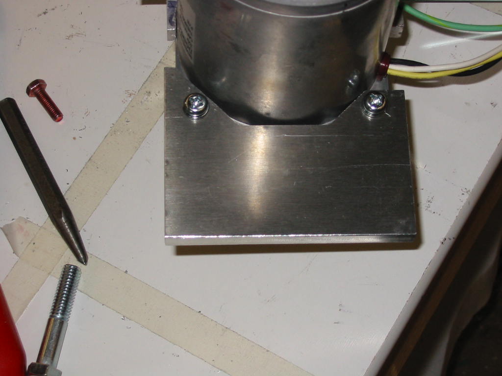
does show the 2 bolts mounted up front to act as a
line guide for the in/out line.
left/right line due to the length changing and was
just more complicated to add.
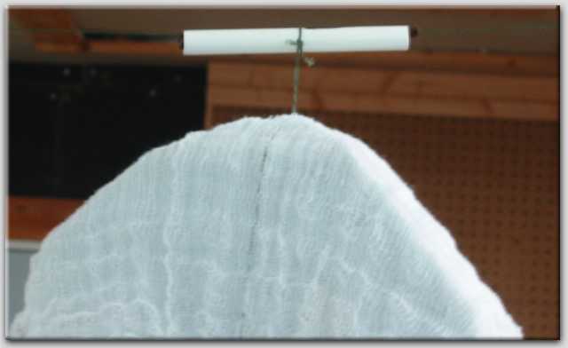
The line travels through a plastic tube instead
which allows the ghost to stop at each end but the
line still travels on. I did add a piece of leather
inside the tube for a little grippage.
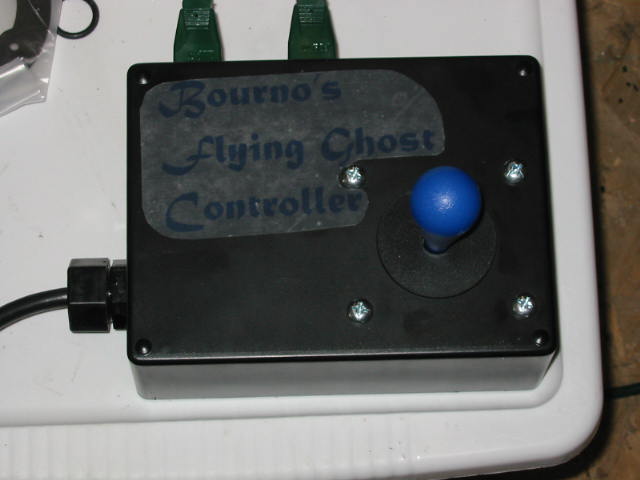
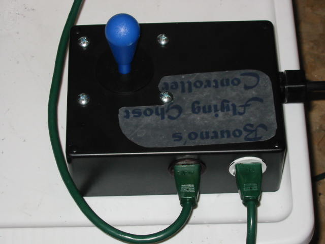
home-made controller. The joystick is from Happ
Controls and the enclosure box was from RadioShack.
Inside, there is a 110 to 12vdc adaptor to provide the
joystick with low voltage for it and then the relays
switch the neutral portion of the motors for the correct
direction running.
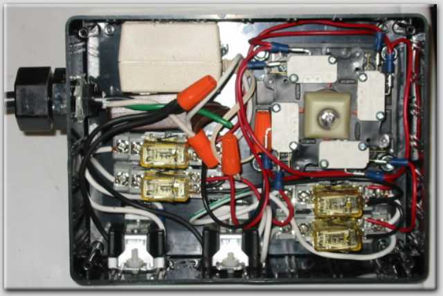
easy to move and plug-in. As below in
the wiring diagram, I did use the green
wire as a neutral and used plastic nuts
and bolts when I mounted the 3 prong
outlets instead of metal ones.
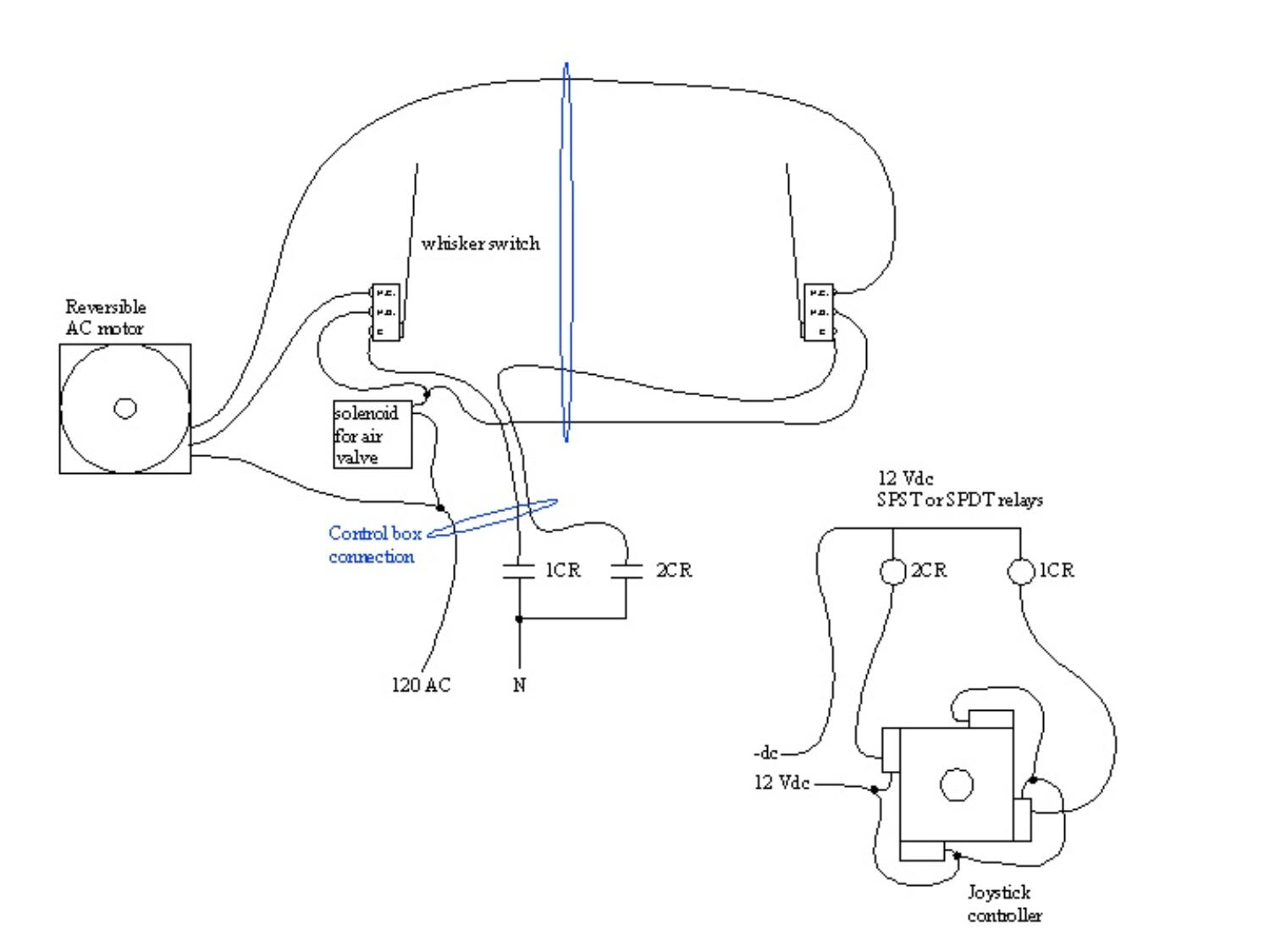
and out to the left/right line motor and limit switches
wiring diagram.
It doesn't show the in/out motor control, but all that
required was another set of 12 volt relays and cord to
control that motor minus the limit switches and solenoid
connections. If you can figure out this drawing, the
in/out wiring should be easy.
NOTE: I did use 3 prong cords for making simple plug
connections and the green wire is NOT an earth ground
any longer, I used it for the second neutral needed for
the reversible motor.