Bourno's How-To Build a Skelerector Page
Page 3 - Rear Bar Assembly
I recommend using 14ga for the 1-1/4" tubing pieces for strength.
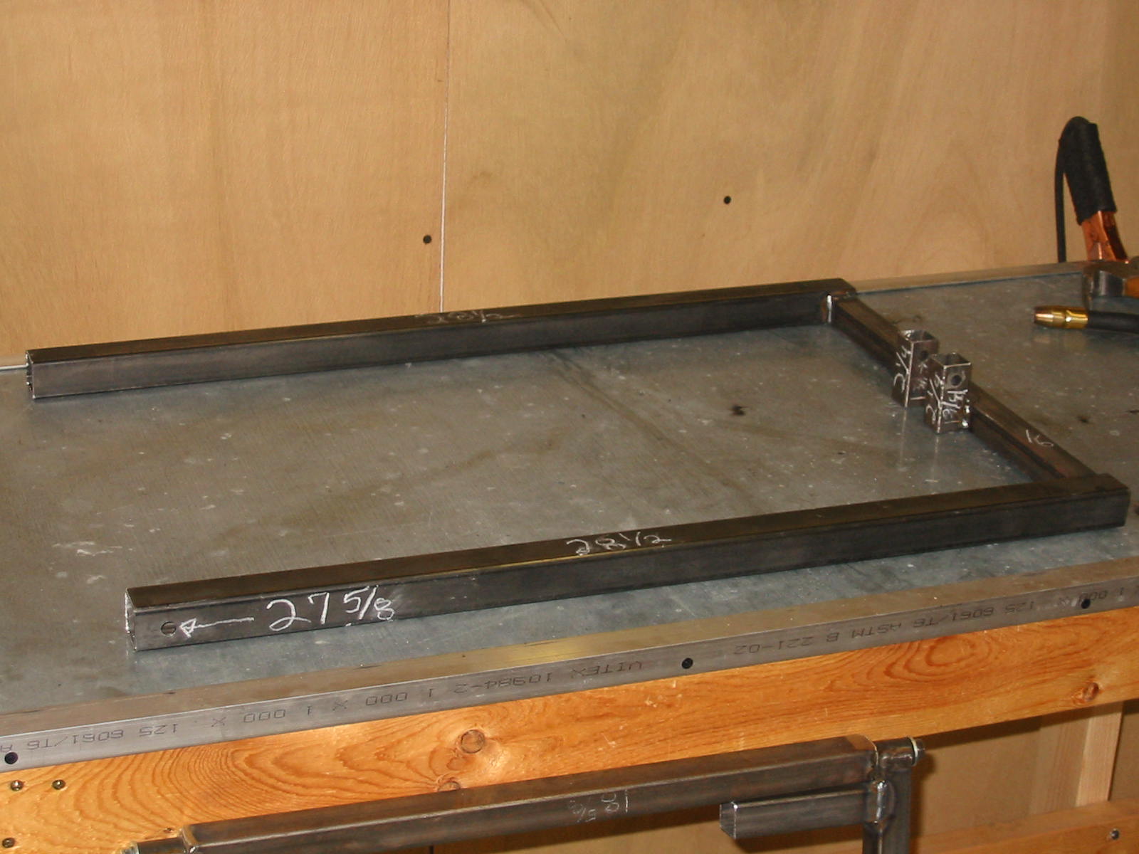
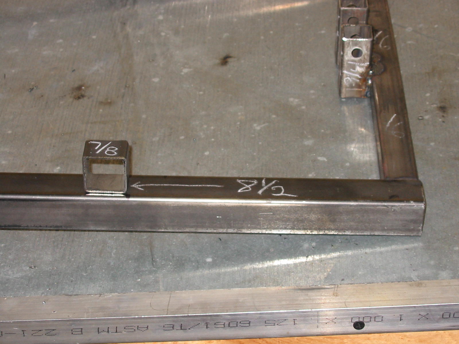
(2) Side bar length - 28-1/2" of 1-1/4" square tubing with a single 3/8" hole centered
27-5/8" from one end of each piece.
(2) Spacer pieces - 2" of 1-1/4" square tubing
(1) Cross bar - 18-1/2" of 1-1/4" square tubing
(1) Cross bar - 16" of 1" square tubing
(2) Attachment pieces - 2-1/4" of 1" square tubing with a single 3/8" hole centered
1-3/4" from one end of each piece.
(2) pieces 7/8" long of 1" square tubing
Rear Bar Assembly Pictures
This is the hardest piece to make. Get this done, and the rest of the
structure is easy.
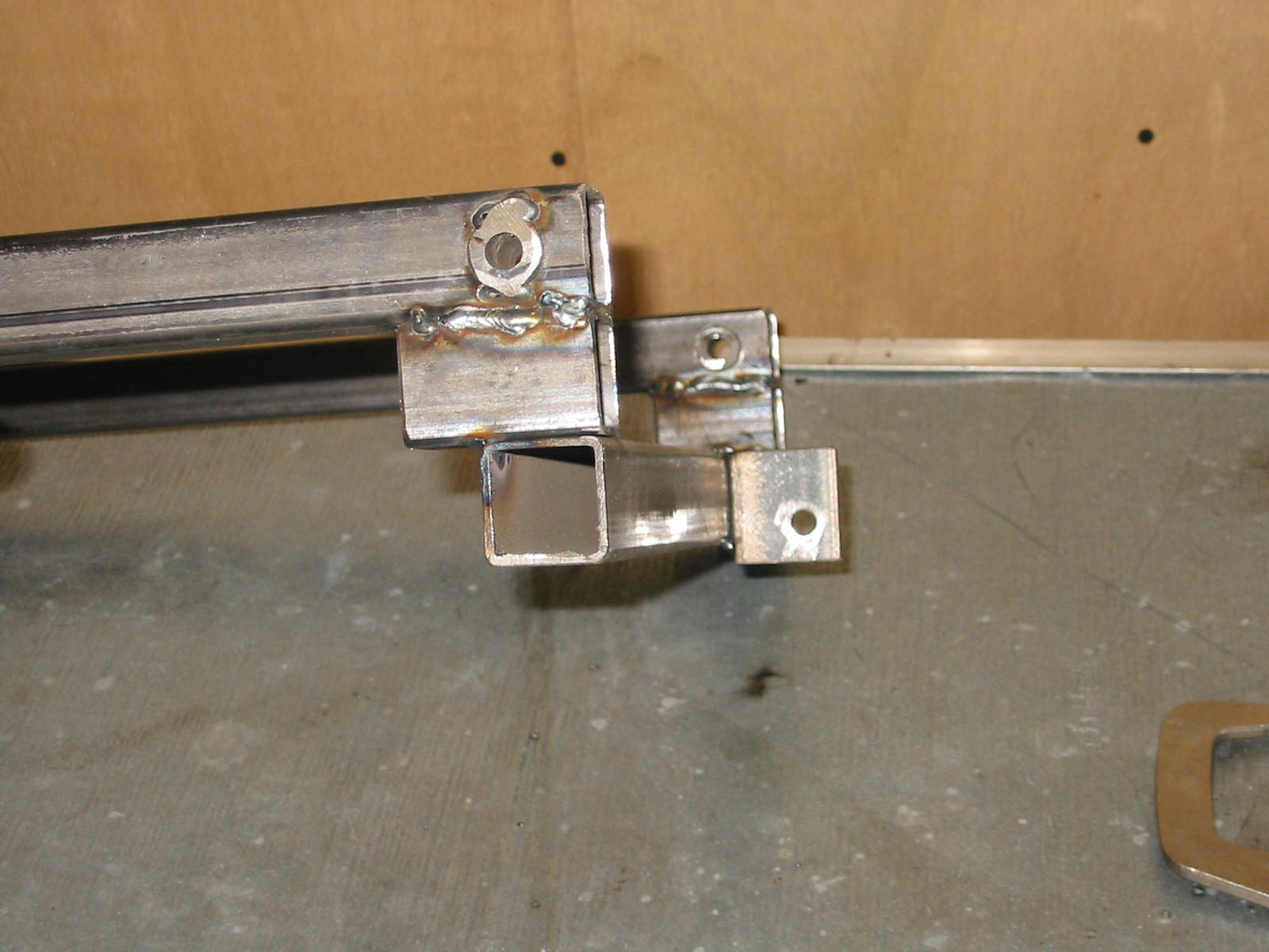
Lay the two 28-1/2" pieces down with the 3/8" hole as shown.
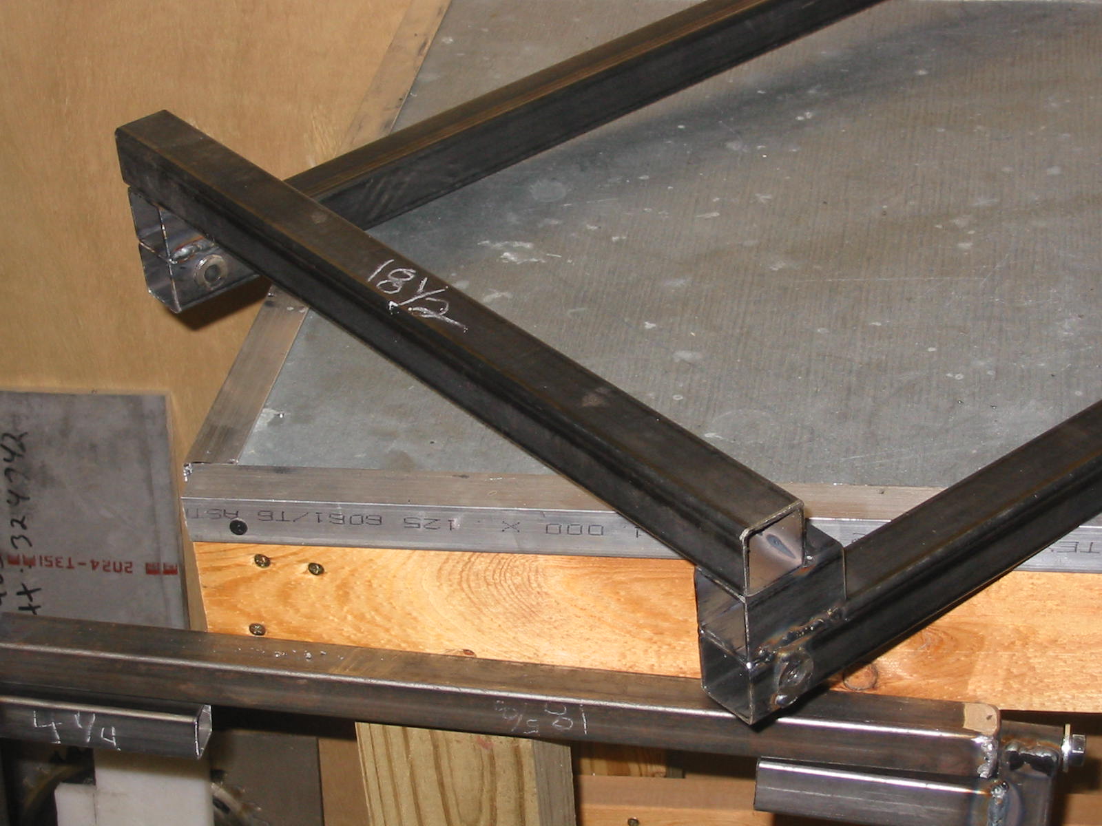
Add the 16" - 1" square piece to the opposite end of the drilled holes.
The 16" piece is in between the 28-1/2" pieces and at the very end.
There will be a 1/4" gap above the 1" tubing at each end since it is
butted up against the 1-1/4" side frame tube.
Square these pieces up and weld them together.
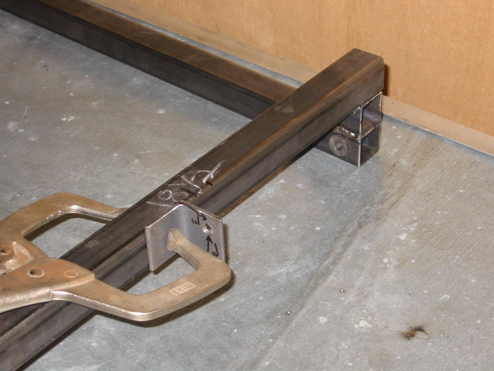
The attachment pieces are located at the inside middle of the 16" piece
with a 1-1/8" spacing between them and with their 3/8" drilled hole
upward as shown in the picture to the left.
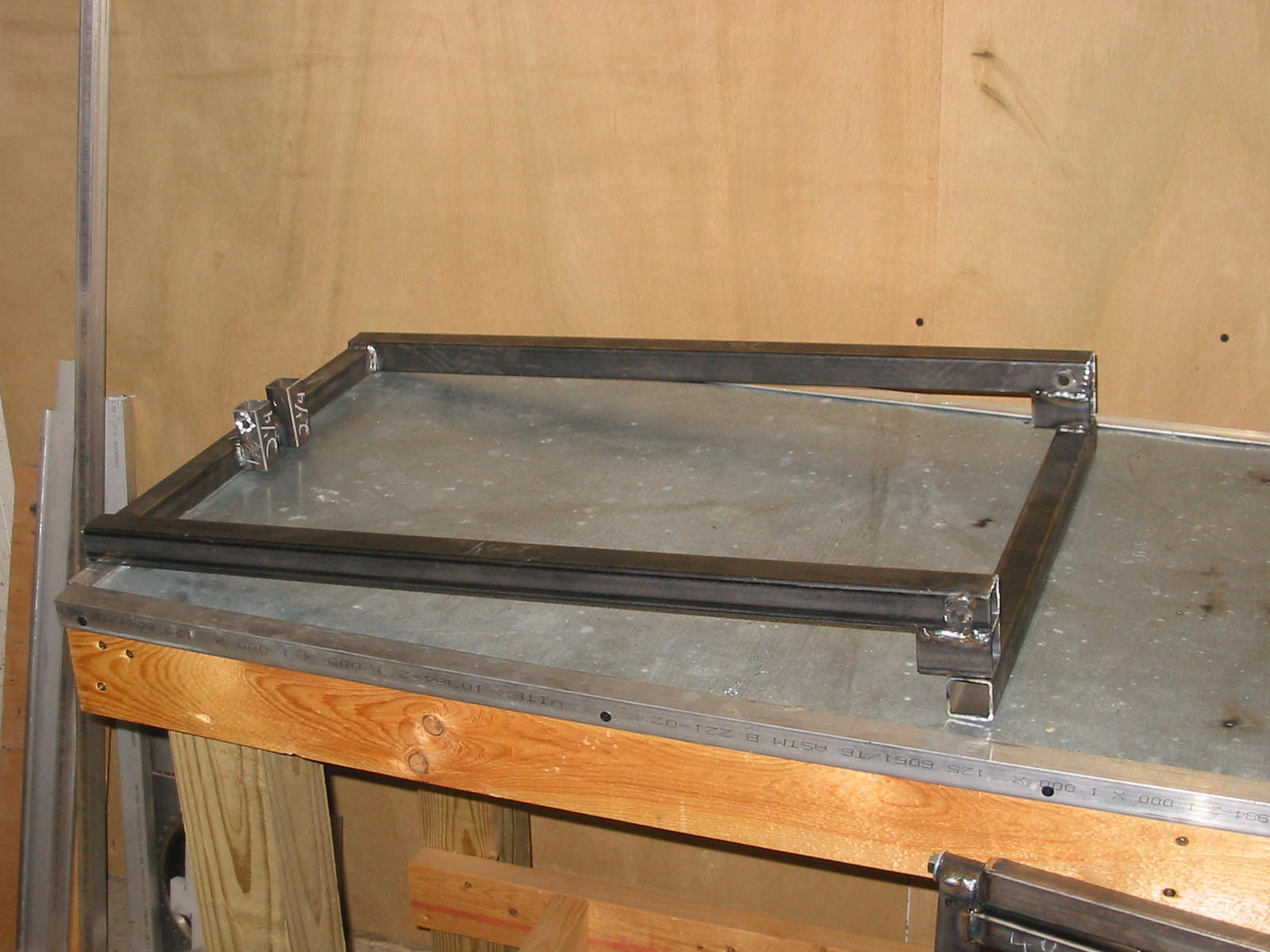
Flip the piece over and add the two spacer pieces and cross piece on
the other end as shown in the picture to the left. These pieces are all
lined up at the end of the 28-1/2" pieces.
See the next picture below for better orientation of the assembly.
This is shown in the proper orientation when we start putting things
together later.
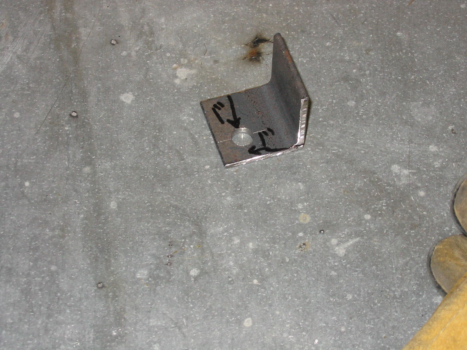
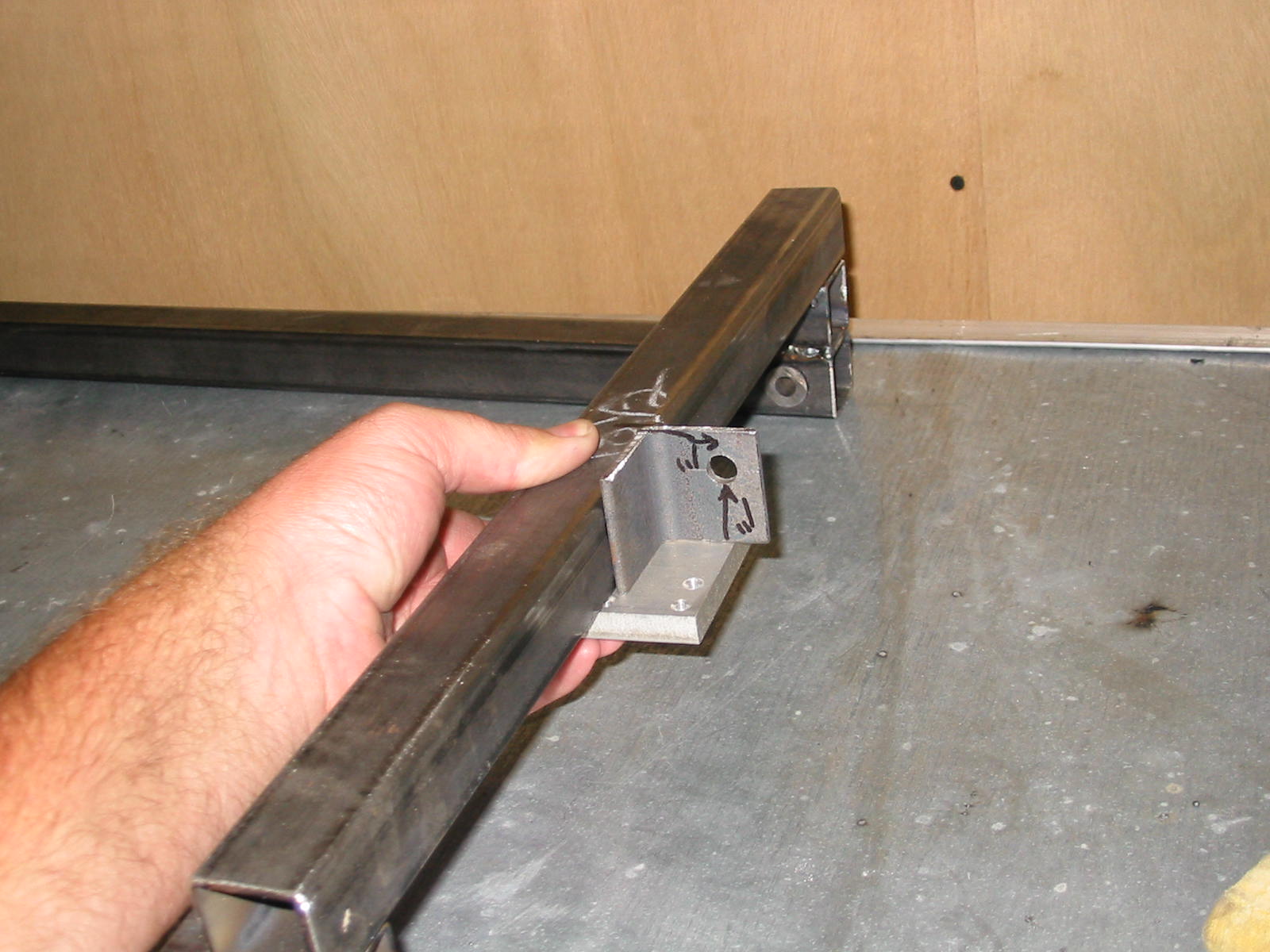
Air cylinder connection - Below shows the proper placement for the clevis connection for
the 5" stroke air cylinder. You can add this later if need be for positioning.
The important part here is the hole is 1" down from the top of the cross
tube and it is 1" out from it. With the 5" stroke cylinder, this placement
will lift and rotate the rear bar to the correct standing position.
I used 2 pieces of 1-1/2" angle on my own set-up.
Add this piece on each side as shown. This block is to keep the 4-bar
linkage from over-centering when the prop is retracted and someone
should try and push the prop down further.