Bourno's How-To Build a Skelerector Page
Page 5 - Base Frame
(2) Side rails - 38" of 1-1/4" square tubing
(1) Cross piece - 19" of 1-1/4" square tubing
(1) Cross piece - 19" of 1" square tubing
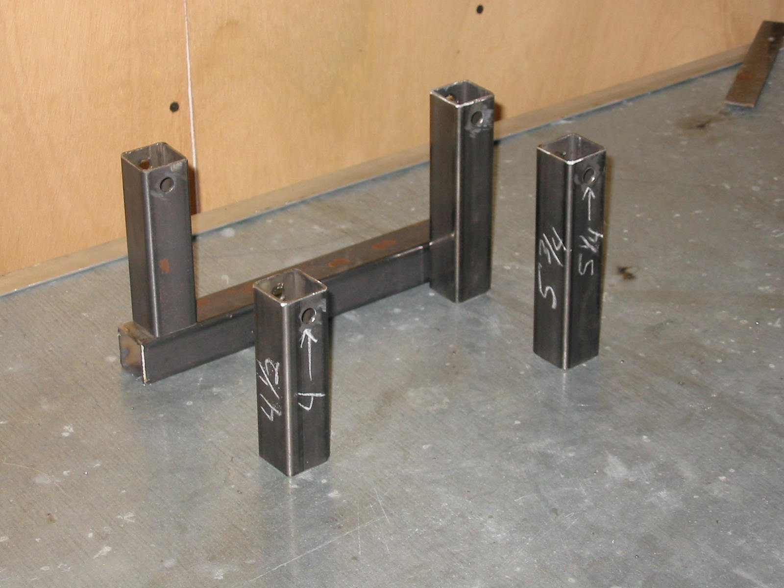
(2) Vertical posts - 4-1/2" of 1-1/4" square tubing with a 3/8" hole centered at 4"
(2) Vertical posts - 5-3/4" of 1-1/4" square tubing with a 3/8" hole centered at 5-1/4"
(2) Cylinder mounts - 3" of 1" square tubing
(2) Rear stop bars - 6-1/4" of 1" square tubing
Some 1/8" x 1" flat strip
Base Frame Assembly Pictures
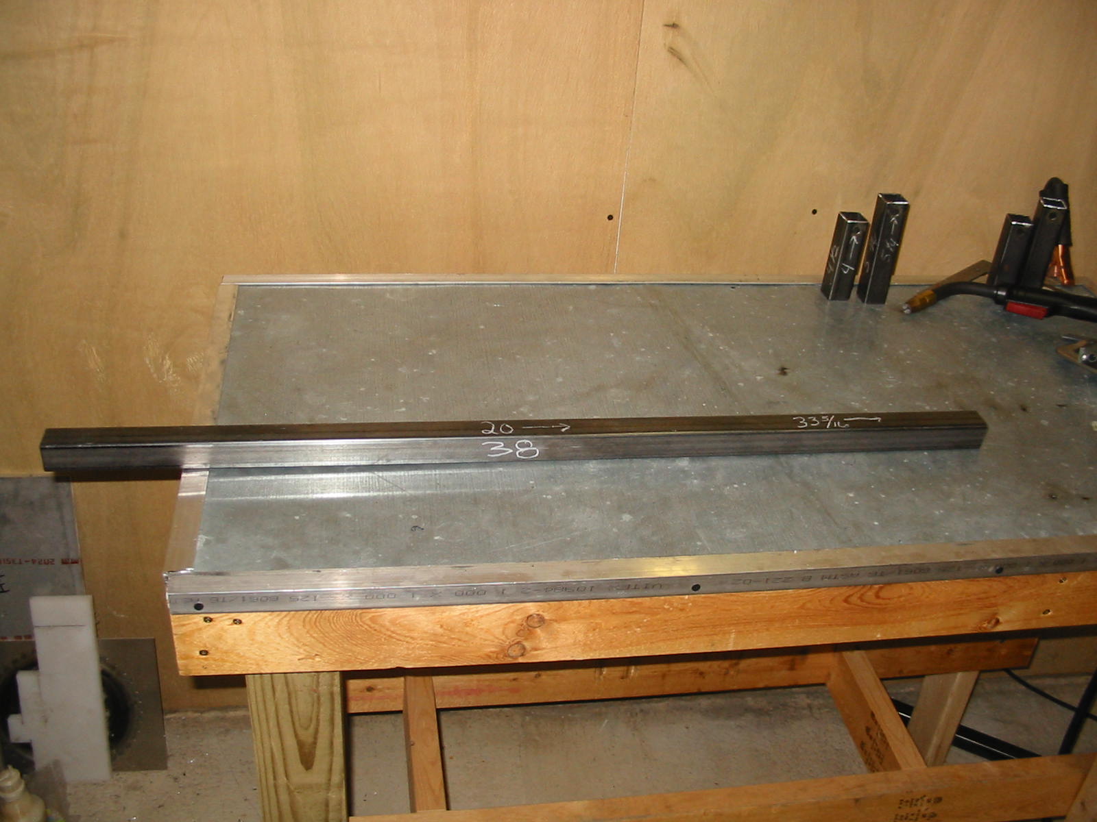
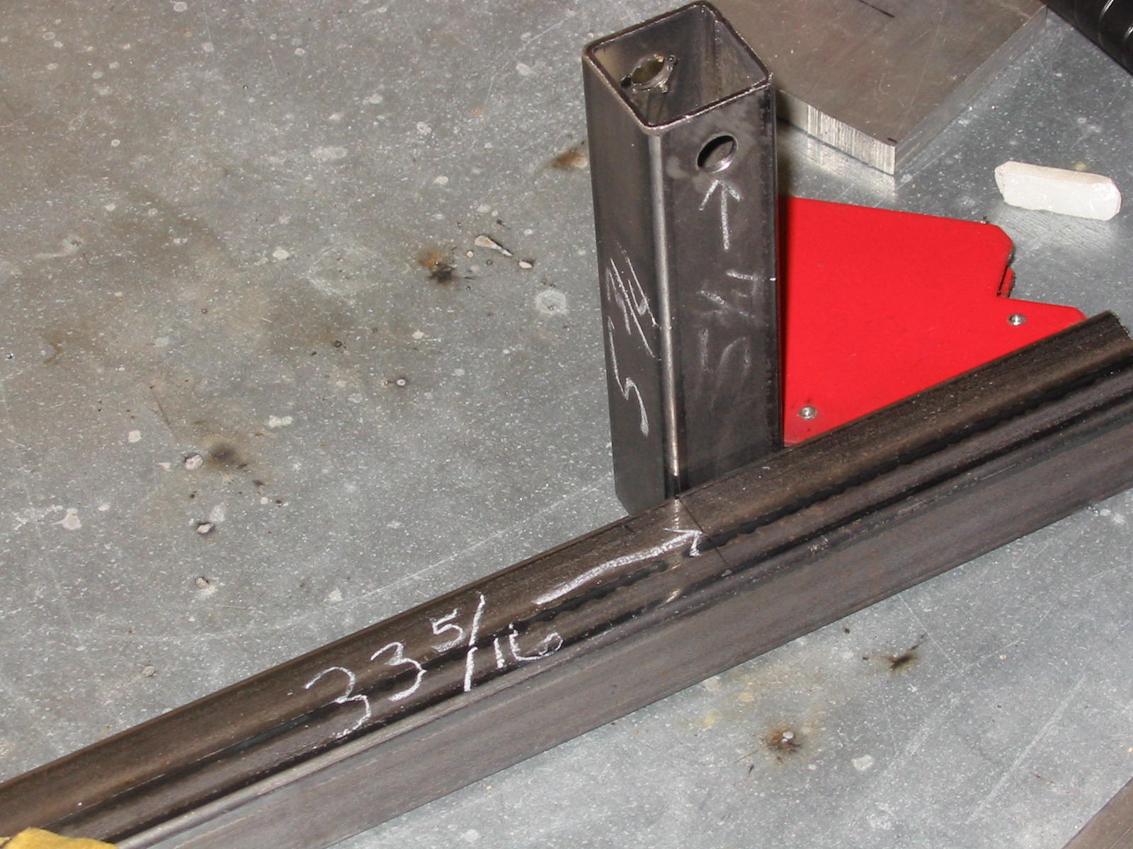
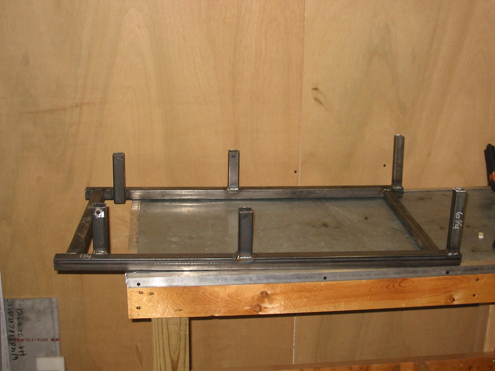
The 4-1/2 and 5-3/4" vertical tubes are placed at the 20"
and 33-5/16" marks on the 38" side rail.
Meaning the 4-1/2" tube is between 20 and 21-1/4" and
the 5-3/4" tube is between 33-5/16 and 34-9/16".
See the following pictures for proper placement as the
4-1/2" is mounted on top of the 38" piece and the 5-3/4"
tube is mounted on the inside of the 38" pieces.
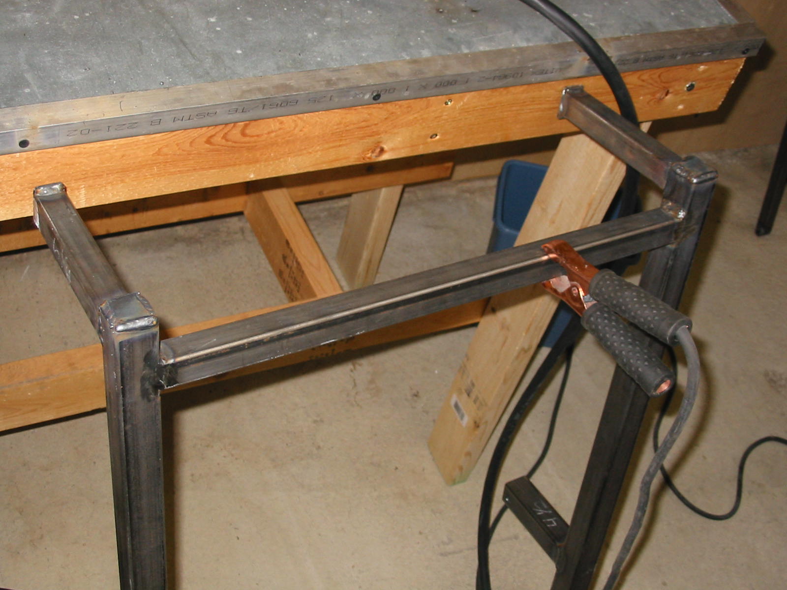
This is the front side of the base frame.
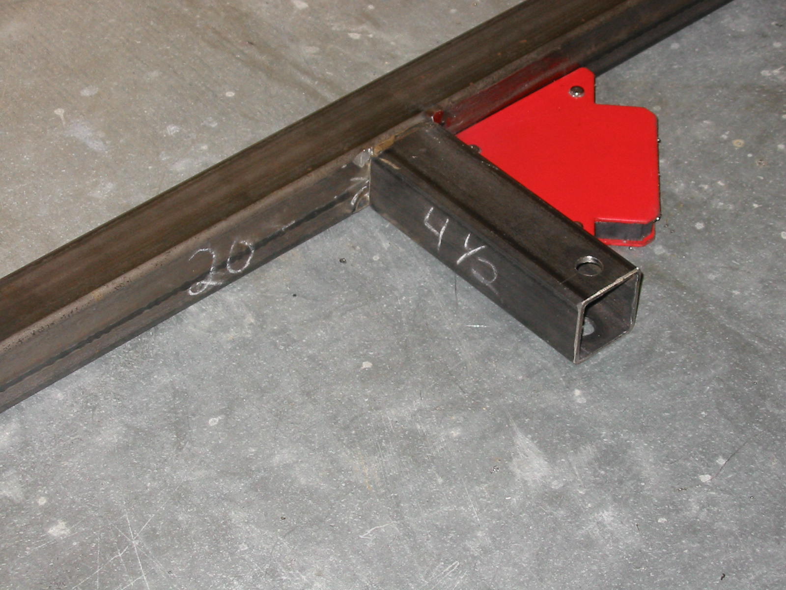
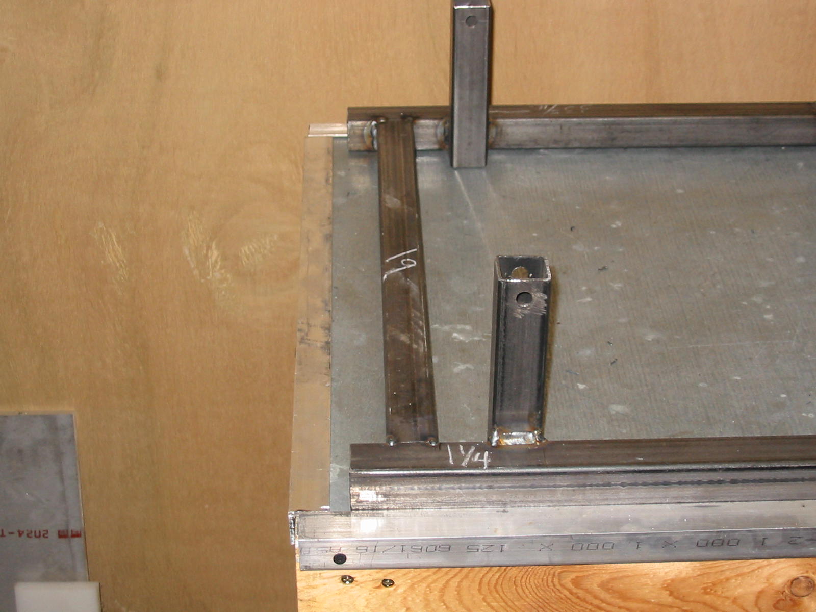
My front 1-1/4" cross tube was placed 1-1/4" in front of the
vertical post. This piece will have air cylinder mounts added
onto it and should be far enough away for mounting most air
cylinders as shown in the pneumatics page.
Make sure to square up the pieces before welding.
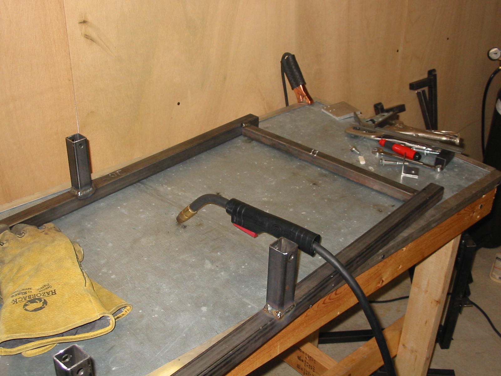
I used a 1" piece for the rear cross member. You could
use 1-1/4" stock if you wanted to. It was placed 1-1/2" in
from the end.
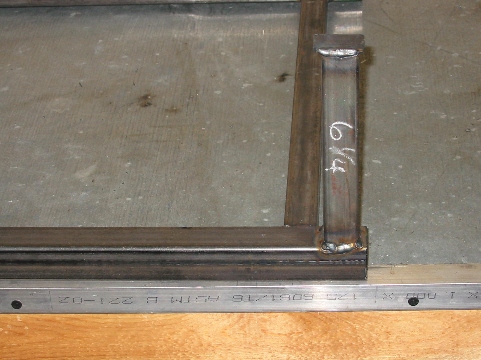
Shown above is the rear stop/support piece for the front
legs. It was placed in 1/4" and a piece of 1/8" strip added
on top of it.
I also welded on ends of the side rails to keep moisture
out since they will on the ground and water could pool
inside otherwise.